


We mainly provide research and training on solar power generation as the main topic for vocational high schools, universities, postgraduates, and corporate technicians.
★ Provide powerful center management software to facilitate equipment management
★ Provide convenient software upgrade and firmware update service
★ Provide database data backup for easy viewing of historical date
★ Padlock function, more convenient maintenance
Inquiry Now

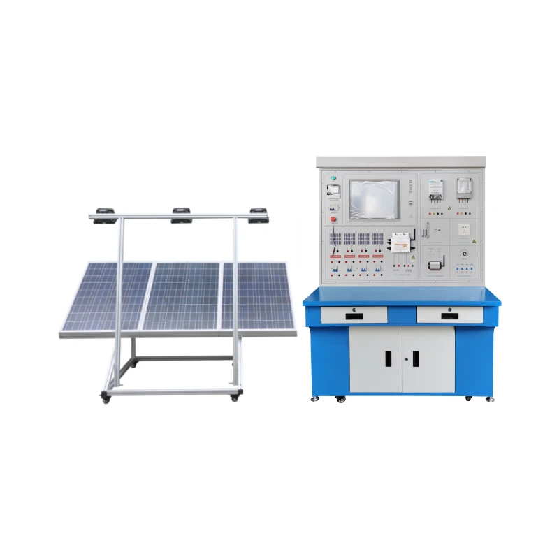
SY-SGT02A Solar photovoltaic grid-connected power generation teaching experiment platform
1. Application scope of system training:
It mainly provides research and training on solar power generation as the main topic for vocational high schools, universities, graduate students, and enterprise technicians.
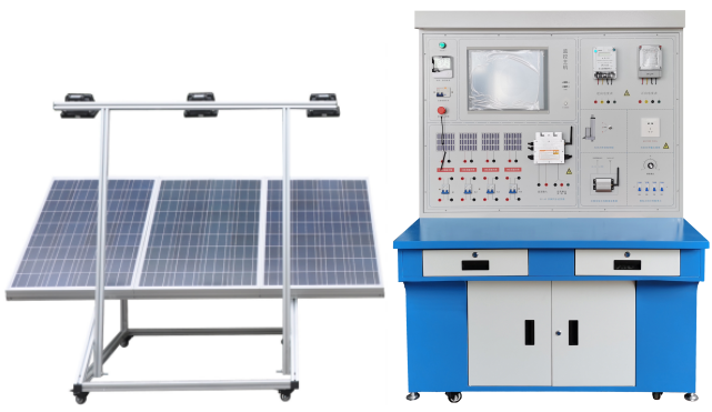
Photovoltaic grid-connected power generation system training platform
2. Technical parameters
2.1. Solar panels
Solar panels are assembled in an array form, mainly composed of 3 (or more) small solar panels, which can realize parallel connection and series connection of solar panels, and then provide two kinds of solar panels with high current or high voltage Networking method.
Maximum output power: 100W*3 blocks
Open circuit voltage: 35V (parallel connection)
Short-circuit current: 4*3.25A (parallel connection)
2.2. Illuminance meter
Range: 0-225Lx, 200-2250Lx, 2000-22500Lx and 20K-225KLx (225000Lx) automatic switching range.
2.3. Technical indicators of environmental monitoring module
Contains illuminance meter, thermometer, hygrometer, single-chip clock system to realize time display
2.4, 17-inch industrial control all-in-one computer with touch function
C P U: Intel 1037U 1.8GHz 22nm dual-core processor TDP 17W ultra-low power consumption processor
Motherboard: Intel M11 industrial control solid-state energy-saving motherboard
Memory: 1G DDR3 1333 ultra-high-speed memory, supports 1333/1066MHz memory, and can support up to 8GB.
Hard disk: 24G SSD solid state drive
Graphics card: integrated Intel HD Graphics core graphics card, providing VGA, LVDS, dual HDMI display output, LVDS supports dual-channel 24bit, supports single display, dual-display copy, and dual-display expansion.
Sound card: integrated ALC662 6-channel high-fidelity audio controller
Network card: Integrates 1 RTL Gigabit network card, supports wake-up on LAN and PXE functions.
Power supply: external power supply (100V to 220V wide range voltage, universal)
Display: 13-inch LED industrial control screen Resolution: 1024*600
Touch screen: Taiwan Military Touchkit 4-wire touch screen, high light transmittance; stable performance, sensitive touch
Machine interface: 4* USB 2.0 interfaces, two of which can support USB3.0 (need to be customized),
1* HDMI interface: 1* VGA interface, 1* RJ-45 network interface, 1* Line out (green), 1* Mic (red)
2*COM serial ports, 1* 12V DC_JACK input interface
system status:
Solar controller (with alarm function):
Data display and dynamic curve display of input voltage, current and power
Output voltage, current, power data display and dynamic curve display
Battery: voltage data display and dynamic curve display
2.5 Grid-connected inverter:
The grid-connected inverter has a DC-DC and DC-AC two-stage energy conversion structure. The DC-DC conversion link adjusts the operating point of the photovoltaic array to make it track the maximum power point; the DC-AC inverter link mainly makes the output current and the grid voltage have the same phase, and at the same time obtains the unit power factor.
The system panel is equipped with multiple test ports for measuring DC and AC related parameters, which can measure the DC-DC voltage and current changes and the voltage and current and curve changes and waveform comparisons during the DC-AC inverter process.
6 levels of power search function
In the process of automatic adjustment, you will see the LOW light flashing non-stop, the power will start from 0, increase the output power to the maximum power point, restart up to 6 times, and then enter the power lock state, and the ST light will be long when locked. Bright.
When performing a level 6 power search procedure, the time required is 10 minutes.
Connect directly to solar panels (no need to connect batteries)
AC standard voltage range: 90V~140V/180V~260VAC
AC frequency range: 55Hz~63Hz/45Hz~53Hz
Grid-connected output power: 300W
Output current total harmonic distortion: THDIAC <5%
Phase difference: <1%
Island effect protection: VAC;f AC
Output short circuit protection: current limiting
Display mode: LED
Standby power consumption: <2W
Power consumption at night: <1W
Ambient temperature range: -25℃~60℃
Ambient Humidity: 0~99%(Indoor Type Design)
High performance automatic power point tracking (MPPT)
Powerful MPPT algorithm to optimize the power collection from solar panels, can accurately capture and lock the maximum output power point, so that the power generation can be greatly increased to more than 25%.
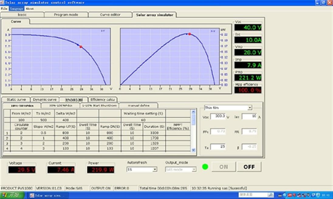
MPPT Tracking Chart
Power output: (reverse power transmission)
Efficient power reverse transmission technology, one of the patented technologies, when the inverter is in the grid-connected output mode, the power is transmitted in the opposite direction, and the load in the circuit is automatically detected and used in priority, and the unused power is transmitted to the grid in the reverse direction Supply to other places for use, the power transmission rate can reach 99.9%. Make the output efficiency higher in the photovoltaic power generation application system.
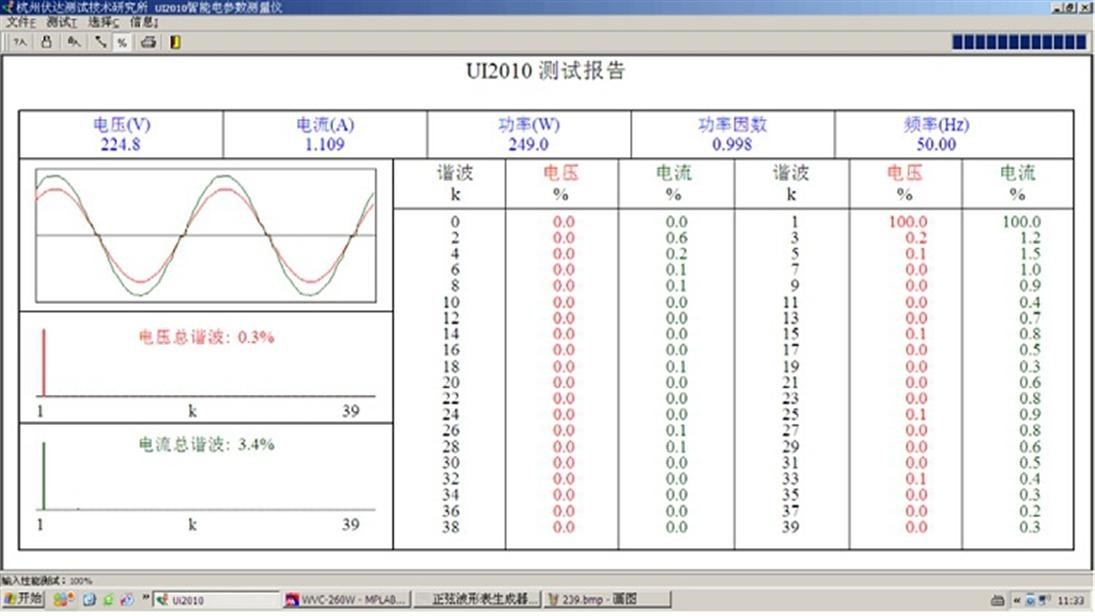
Grid-connected wave component test chart
Intelligent classroom comprehensive measurement and control system (this system adopts an integrated design, which requires the above functions to be concentrated on a core controller, and the assembly of various modules is prohibited to ensure the personal safety of users and the performance indicators of equipment safety):
(1) Functions to be realized by the virtual oscilloscope:
50MHz 2-channel waveform measurement function;
(2) 2-way logic analyzer function;
(3) 1 channel arbitrary waveform signal generator output;
200MSa/s high-speed real-time sampling, 50MHz bandwidth, waveform measurement fully meets the requirements of teaching experiments, and the waveform is smooth and undistorted.
(4) 2-way PWM pulse signal generator: frequency and duty cycle can be set.
(5) Multimeter function
1. The resistance measurement function of the multimeter;
2. The DC voltage measurement function of the multimeter;
3. The AC voltage measurement function of the multimeter;
4. The AC current measurement function of the multimeter;
(6) Man-machine interface function
*1. The man-machine interface displays the measured waveform and displays the corresponding measurement value;
*2. By clicking the interface button, the measured waveform can be inserted into the experiment report template;
*3. The results of students' experiment reports can be uploaded to the designated teacher's computer folder by clicking the interface button;
(7) Laboratory safety monitoring function
1. Environmental parameter measurement: It can measure and display temperature and humidity, CO2 concentration and PM2.5 at the same time;
2. Electrical parameter measurement: It can measure the voltage and current of the console, and calculate the power;
3. Overcurrent, overvoltage, undervoltage (threshold can be set) alarm trip protection;
4. Safety protection: laboratory environment safety monitoring device (PM2.5, smoke, combustible gas, temperature and humidity and abnormal CO2 concentration (fire alarm) alarm);
5. Power-saving function: when no one is experimenting for a long time, the main switch will be automatically turned off to achieve safety and power-saving effects;
2.6 Intelligent Control System for Safe Electricity Utilization in Laboratory Based on Internet of Things
1. Features
When the intelligent control system detects that there is an electric leakage or electric shock, the intelligent control system will disconnect in 0.1 second to ensure personal and property safety; the intelligent control system itself has a fault indicator light, and the user can judge according to the fault indicator light of the intelligent control system The current fault status is easy to handle; the intelligent control system has a padlock function, and when maintenance is required, lock it at the padlock position to prevent others from powering on, making maintenance safer. It can collect on-site output device data and upload it to the cloud through a variety of Internet of Things communication methods to realize remote monitoring of local devices.
2. Function
Based on the intelligent control system for safe electricity use in the Internet of Things laboratory, it can collect, count, store, analyze, query, etc. electricity data. Use front-end data visualization technology to display real-time power consumption data on the platform, and provide visual power consumption information query function in the form of charts; use database technology to monitor the operation status of power consumption equipment and lines in real time, and give timely alarms for abnormal conditions, thereby Prevent electrical fires; use power system fault location technology to timely discover and accurately locate power fault points, automatically generate fault reports, and assist users in repairing power system faults in the first place; use power quality monitoring technology to analyze and evaluate power quality problems in real time, And provide customized governance solutions to help users obtain high-quality electric energy; use big data technology and industry mathematical models to count, analyze and mine basic electricity consumption data, and explore energy-saving potentials based on data to provide energy efficiency optimization solutions. To meet the needs of the power management system for visible, safe, reliable, high-quality and economical smart power modules.
3. The intelligent control system for safe electricity use in the laboratory based on the Internet of Things is composed of an executive device and a network machine. The technical parameters are:
(1) Technical parameters of the actuator
(1) Number of poles: 3P+N
(2) Tripping characteristics: C (5-10) In D (10-14) In
(3) Rated current: In 6A, 10A, 16A, 20A, 25A, 32A, 40A, 50A, 63A
(4) Rated voltage: Ue AC 230V/400V
(5) Rated frequency f: 50Hz
(6) Rated short-circuit breaking capacity: Icu10kA
(7) Frame grade rated current: Inm63A
(8) Phase loss protection: device anti-burn protection mode
(9) Leakage protection: component damage protection mode
(10) Overload protection: overcurrent anti-burn mode
(11) Short circuit protection: touch line anti-burn mode
(12) Padlock protection: easy maintenance and safety
(13) Over-temperature protection: can monitor line temperature
(14) Overvoltage and undervoltage protection: prevent personal accidents and mechanical equipment damage
(15) Disconnect in 0.1 seconds when electric leakage or electric shock occurs
(16) Fault indicator light, easy to check the working status
★(17) Padlock function, more convenient maintenance
(2) Network machine technical parameters
(1) Built-in STM32F103C8T6 main control chip
(2) External 8M passive crystal oscillator
(3) Use SP3485 as the 485 communication chip
(4) 485 anti-surge protection
(5) Standard RS485 interface, can be directly serial device
(6) Intelligent data terminal, convenient to realize data transmission function
★(7) Provide powerful center management software to facilitate equipment management
★(8) Provide convenient software upgrade and firmware update service
★(9) Provide database data backup for easy viewing of historical data
(10) Size: 89mm*67.5mm*20.5mm
(11) Weight: 70g
(12) Power supply: AC220V
(13) Power consumption: 1.5W
(14) Working temperature: -25°C - +70°C
(15) Working humidity: 95%
(16) The maximum downlink transmission rate of the WiFi version: 64kbps
(17) Maximum uplink transmission rate of WiFi version: 32kbps
3. Teaching and research training projects
2.1. Photovoltaic energy conversion experiment
Experiment 1. Composition principle of photovoltaic array unit.
Experiment 2. Combination principle of solar photovoltaic cell energy conversion.
Experiment 3. The principle of array electronic maximum power tracker.
Experiment 4, the principle of array confluence and lightning protection grounding.
Experiment 5, array structural parts, anti-corrosion installation principle.
Experiment 6. Maximum power tracker and photovoltaic conversion efficiency improvement experiment.
Experiment 7. Experiments on the influence of light waves on photovoltaic conversion efficiency under different weather and sunlight intensities.
Experiment 8. Experiments on the influence of solar orbit changes on photovoltaic energy conversion in different seasons.
Experiment 9. The experiment on the influence of photovoltaic energy conversion under the change of ambient temperature in different seasons.
Experiment 10, the energy conversion experiment after the low, medium and high arrays are combined by switches.
Experiment 11, the actual effect experiment of the light sensor and the wind speed sensor.
2.2. Synchronous inverter power supply experiment
Experiment 1. Composition principle of inverter power unit.
Experiment 2. The experiment of the maximum power tracking control method of the inverter power supply MPPT.
Experiment 3. The experiment of inverter output power and photovoltaic energy conversion.
Experiment 4. Comparative experiments on effective combination and separation control of MPPT and electronic tracker.
Experiment 5. Comparative experiments on the waveform, harmonic content and power factor of the alternating current output by the inverter power supply in sunny, cloudy and rainy days.
Experiment 6. The power supply of the grid where the inverter is integrated is interrupted. The inverter should stop supplying power to the grid within 2s, and at the same time send out a warning signal for anti-islanding effect protection test.
Experiment 7. Inverter DC input undervoltage control experiment.
Experiment 8. The input voltage is the rated value, and the noise test experiment is carried out at a distance of 1m from the horizontal position of the equipment when the load is fully loaded.
2.3. Photovoltaic grid-connected power generation system software experiment
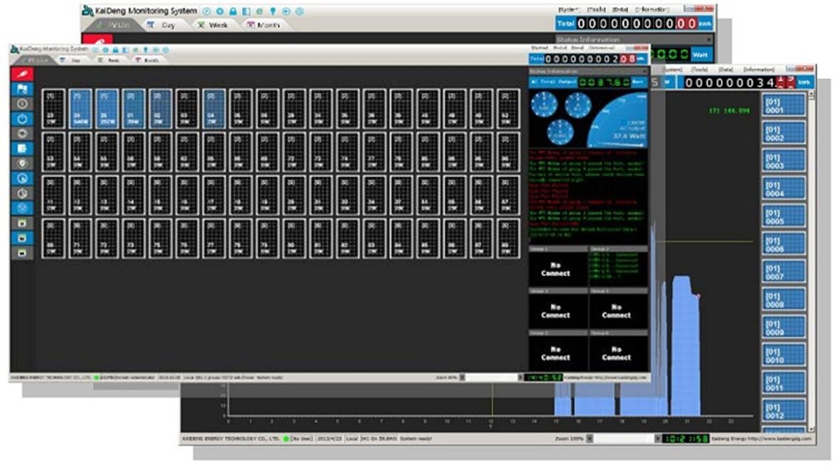
Experiment 1. View single-station monitoring items in the host software:
◆ DC voltage VDC, DC current A, input power KW
◆ AC voltage VDC, AC current A, output power KW
◆ Daily power generation KWh, daily operating hours h min, total power generation KWh, total operating hours h, Co2 emission reduction Kg
◆ System running status normal/abnormal
◆ System operating temperature Normal/abnormal
◆ The system monitors the status of the PC, normal/abnormal
◆ System power test curve
Experiment 2. Check the power record items of a single station in the host software:
◆ Device number No. 1 machine:
Daily power generation degree, daily operating hours h min, total power generation degree, total operating hours h
Experiment 3. View single-station fault record items in the host software:
◆ Device number No. 1 machine:
DC overvoltage, DC undervoltage, DC overcurrent
AC overvoltage, AC undervoltage, AC overcurrent
System overload, frequency abnormality, island protection, ADC abnormality (quickly detect grid-connected voltage and current), IPM fault, overcurrent protection, overtemperature protection, temperature abnormality, DSP abnormality (digital signal processor, convert analog signal to digital signal )
4. Operating technical conditions (single-phase output)
◆ Photovoltaic array output voltage 17.5~40VDC
◆ Grid-connected output voltage 180~260VAC
◆ Grid-connected frequency range 47.8~51.2Hz
◆ Efficiency 94.5%
◆ Power factor>0.99
◆Maximum power tracking 10.8~28VDC
◆ Working environment: Temperature -20℃~50℃
◆ Relative humidity﹤90﹪(25℃)
◆ Protection function: Lightning protection, reverse polarity, short circuit, leakage, overheating, island effect, overload protection, grid overvoltage and undervoltage, grid overfrequency and underfrequency protection, ground fault protection, etc.
3. System unit composition
3.1. Photovoltaic array unit: Build a platform or balcony of about 3 square meters outdoors, install brackets, and lay a photovoltaic array with a total peak power of 300W. When conditions permit, the photovoltaic array can choose three different types of solar cells for experiments (monocrystalline silicon, polycrystalline silicon, amorphous silicon).
3.2. Inverter control unit: According to the needs of the experiment, the system can realize at most 3 units of different models and origins connected to the grid through the opening and closing of the switch unit The inverters run at the same time, equipped with simultaneous grid-connected channels, which can meet the needs of comparative experiments and various data collection.
3.3. Switch control unit: the lead wires of all internal and external units of the system are connected to their respective jumper terminals through the isolation switch. To protect instrumentation and personal safety.
3.4. Square array connection unit: on the wiring panel, the lead wires of the smallest unit are connected to their respective jumper terminals through the isolation switch. According to the needs of the experiment, jumpers can be used to freely combine different open circuit voltages of 17.5-60VDC, peak Power 50 ~ 300W system.
3.5. Display unit: square array voltage and current. Reverse AC voltage, current, frequency, power, reactive power. Forward AC voltage, current, frequency. Equipment working temperature, battery array temperature, laboratory temperature and humidity, experiment timing clock, reverse electricity metering, forward electricity metering.
3.6. Grid-connected monitoring unit: The monitoring device includes a monitoring host, monitoring software and display equipment. This system uses a high-performance industrial control PC as the monitoring host of the system, configures the multi-machine version monitoring software of the photovoltaic grid-connected system, and adopts the RS485 communication method to obtain the operating parameters and working data of all grid-connected inverters in real time.

If you have any questions, please leave a message, we will reply as soon as possible.
Send Message